
YFL Globe Valves Operation and Maintenance Manual
Content
1. Generalities
2. Safety instructions
3. Transport and storage
4. Description / Documents
5. Installation
6. Operation / Putting into and out of operation
7. Commissioning / Maintenance
8. Troubleshooting
9. Guarantee
1. Generalities
The following operation instructions are valid for YFL globe valves, which serve to shut the flow of liquids, gases and steams in pipe lines, and of course to let it through, whenever they are in OPEN status.
By a correct assembling, maintenance or repair we guarantee an activity free of troubles. The manufacturer carries no responsibility for efficiency and safety of the valves, whenever these operating instructions are not observed and accurately.
These operation instructions do not take into consideration:
- Any accident and incident which can arise by assembling, operation or commissioning of the valves.
- Any safety rule in relation with the place where the valve is installed. The operator is responsible for the observation of the safety rules, - also by the assembling staff.
The connected loads prescribed for driven valves, as well as the instructions for assembling, commissioning and operation have absolutely to be observed.
It is essential that the globe valves are handled by skilled staff that must be aware of the interactions between the valves and the system in which they are installed.
An incorrect use of a valve may cause strong consequences to the complete system, such as:
- Escape of medium
- Stop of the unit
- Affects, decreases or increases of operation or work of a system or unit.
For any further inquiries or in case of damage, please contact YFL Flow Control Co., Ltd.
2. Safety
These operation instructions contain essential information that has to be observed by assembling, operation and commissioning of the globe valves.
For this reason they have to be read by the assembling staff, by the skilled staff and by the operator before the valve is assembled and put into operation and they should always be kept in the proximity of the valve.
Not only the general safety rules indicated in this main paragraph have to be observed, but also the other ones indicated in other paragraphs.
2.1 Indication of notes in the operation instructions
The safety warnings contained in this operation instruction, which have to be observed in order to avoid injuries to persons, are indicated by the following general and particular picot-graphs:
Warning!
Security signal acc. to DIN 4844 W 9
In order to avoid defects of valve efficiency and of its accessories the following warning mark has to be observed:
The signs marked directly on the valve (such as DN) have absolutely to be considered and kept in a readable condition.
2.2 Dangers that can result if safety instructions are not observed.
If the safety instructions are not observed injuries to persons, environment and valve, or system can arise and the indemnity rights get lost.
In particular the non-observance of the safety notes can cause dangers such as:
- Break down of important functions of the valve or unit
- Failure of prescribed methods of commissioning and handling
- Danger to persons caused by electrical, mechanical and chemical impacts.
- Environmental injuries caused by a leakage of dangerous materials.
2.3 Working with safety consciousness
The safety instructions included in this paper, the national regulations for prevention of accidents, as well as the internal regulations referring to work,operation and safety have to be observed by the operator.
2.4 Safety instructions for the operator / user
- When ever some hot or cold valve parts (f. ex. Casing parts or handwheel) may cause any danger, these parts have to be constructed in a way that they are protected from contacts.
- The contact protection for moving parts (such as coupling) must not be taken away while the machine is working.
- Leakages (f. ex. in spindle gaskets) of dangerous conveyed materials (explosive, toxic, hot) have to be removed in a way that no danger to persons or environment can arise. Legal de-terminations must be respected.
- Injuries by electrical energy have to be excluded (please find details to this point in the local power supply enterprise regulations).
2.5 Safety instructions for commissioning, inspection and assembly works.It must be provided that all commissioning, inspection and assembly works are executed by skilled staff, who must have previously studied these operation instructions.
Basically when any kind of work on a valve is executed, the valve has to be cooled down and free of pressure and the evaporation temperature of the medium must be lower than the temperature of all parts it gets in contact with.
Also basically, works on a valve have to be executed when it is stopped. The procedure to stop a valve operation is described in this paper and has absolutely to be observed.
Valves which get in touch with health injuring media have to be decontaminated.Immediately after the work is done, all safety and protection devices have to be put into position or operation again. Before putting the valve into operation again, the points referring to paragraph 6
2.6 Arbitrary reconstruction and manufacture of spare parts
Reconstructions or modifications of the valve are only acceptable under agreement with the manufacturer. The use of original spare parts and by the manufacturer authorized accessories promotes safety. If any damage is caused by using other parts the liability for the consequences can be cancelled.
2.7 Inadmissible operation modes
A safe operation is only guaranteed if the valve is used according to the determinations included in the “generalities” of this operation instruction. The limits included in the technical documentation must not be exceeded.
3. Transport and storage
3.1 Corrosion protection
3.1.1 Carbon steel globe valves
Valves made out of unalloyed or low alloyed cast steel are painted with a hard sticking primer made of a 2-components colour based on epoxy resin paint. The minimum film thickness is 70 μm. The inner surfaces are free of paint and only coated with a temporary corrosion protection (e.g. oil). Machined flange facings are protected against outside influences with a strippable vanish.
3.1.2 Stainless steel globe valves
Valves made out of stainless steel will be delivered without coating.
3.2 Transport
The valves are delivered in a closed condition and its connecting holes are shut up by cover caps. Valves will be supplied as ready for operation.
During transportation and storage valve have to be closed. Connecting holes have to be shut up by suitable means (cover caps, foils) in order to avoid any damage to the valve seats.
In order to avoid damages the valves must not be hanging on the handwheel, or on a possible connected motor or on any other accessory.After delivery, respectively before assembly the valves have to be inspected in order to exclude any transportation damage.
Transport or lifting a valve for installation in horizontal pipe lines as picture 1.
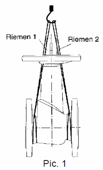
The lifting belts 1 und 2 must be twisted round the body. In order to keep the valve in the shown position and to prevent falling vertically, the two lifting belts should lead to the hook through the handwheel arms. Valves must not be lifted by the handwheel!
3.3 Storage
The storage has to be effected in a way that it can work perfectly even after a longer storage period.
For this purpose it is necessary
- To keep the valve closed (in order to protect the seat facings)
- To take measures against soiling (dust, sand, mortar, respectively building materials), frost and corrosion using plastic foils.
When storing valves with soft gaskets (of elastomer) the storage regulations for elastomer have to be observed:
- The store must be dry, free of dust and moderately ventilated. Store temperature should not go over 25°C..
- stocks on hand have to be used up in order to avoid long storage periods.
- As already mentioned above, the valves have to be in “closed” position during the storage. However the soft closure elements should be shut with little power, in order to avoid a rush aging of the elastomer.
4. Description / documents
4.1 Structure and standards
Bolted bonnet, outside screw and yoke, Rising handwheel,Basic design acc. to DIN 3356 (for ANSI valves,acc. to BS 1873) Flanges acc. to EN 1092-1 (for ANSI valves,acc. to ASME B16.5) Face to face acc. to EN 558 (for ANSI valves,acc. to ASME B16.10) Test:EN12266-1(for ANSI valves,acc. to API 598)
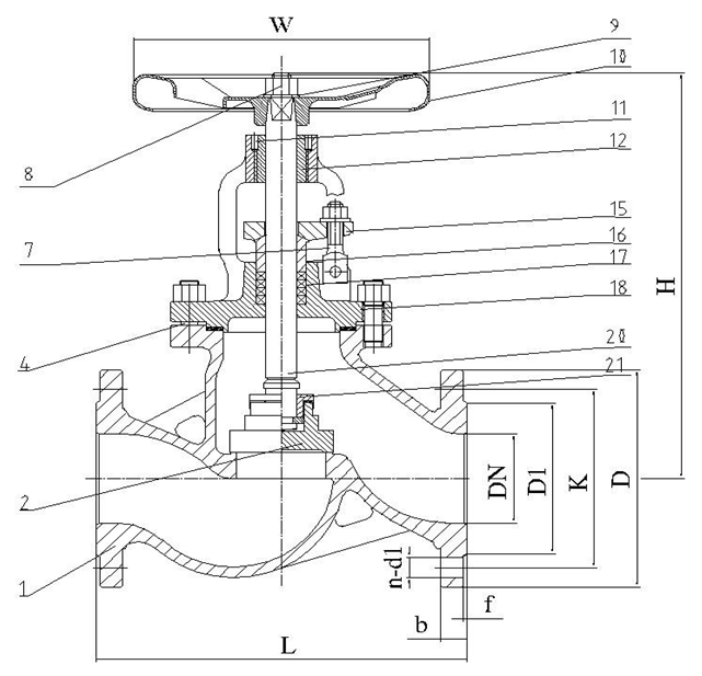
4.2 General view and parts list
|
NO. |
Part |
Material |
|
|
1 |
Body |
1.0619 |
1.4408 |
|
2 |
Disk |
1.4021 |
1.4401 |
|
4 |
Bolt |
1.7258 |
A4 |
|
7 |
Bolt |
35 |
1.4571 |
|
8 |
Nut |
35 |
A2 |
|
9 |
Gasket |
35 |
1.4408 |
|
10 |
Handwheel |
C10E |
C10E |
|
11 |
Bolt |
35 |
1.4401 |
|
12 |
Yoke nut |
0.7040 |
0.7040 |
|
15 |
Gland |
1.0619N |
1.4408 |
|
16 |
Packing gland |
1.4021 |
1.4401 |
|
17 |
Packing |
Graphite |
Graphite |
|
18 |
Bonnet |
1.0619 |
1.4408 |
|
20 |
Stem |
1.4021 |
1.4571 |
|
21 |
Disc nut |
1.4301 |
1.4401 |
4.3.1 Body material suitable for Temperature as follow:
a. Carbon steel 1.0619: -29℃~+425℃
b. Carbon steel WCB: -29℃~+425℃
c. Stainless steel 1.4408: -196℃~+540℃(for flanged connection valves)+815℃(for carbon content≥0.04%)
d. Stainless steel CF8M: -196℃~+540℃(for flanged connection valves)+815℃(for carbon content≥0.04%)
4.3.2 Gasket material suitable for Temperature as follows:
a. PTFE: -180℃~+200℃
b. Flexible graphite: -200℃~+570℃ (Oxidizing medium)
+800℃ (Non-oxidizing medium)
c. Metal sealing circle the same as 4.3.1
4.4 Medium
Valves and pipe lines working in high temperatures (>50°C) or low (<0°C) must be protect from touch by insulating. Alternatively the danger must be indicated by warning boards on the valve side.
If in air-conditioning, cooling and refrigerating systems any condensation water, respectively danger of icing appears, a specialistic and diffusion-tight insulation of the whole valve, if necessary including the handwheel, has to be provided. Icing causes a blocking of the valve operation capabilities.
If a globe valve is mounted in a pipe line as an end valve it has to be secured by convenient measures from an unauthorized or unintended opening. It can also be shut by a blind flange on the exit side, in order to prevent any injury to parts and / or persons.
5.2 Installation position
All handwheel operated valves are designed in such a way that turning the handwheel clockwise, valve closes and turning anticlockwise valve opens. In relation to the stem direction, globe valves can be installed in any position. They are preferably to be installed with the stem in vertical upright position.
The prescribed flow direction for globe valves is in such a way that pressurization is under the disk.
5.3 Welding instructions / pipe line assembly
For welding works on the valves the pipe line manufacturer is responsible.
Whenever the valves with butt welding ends or socket weld ends are welded and during welding works at the pipe line with already installed valves, it has to be taken care that no impurity get inside of the body or even stay there, otherwise the seat facings and the stem sealing can be damaged.
If welding works are done in the proximity of soft seated valves, it has to be taken care that the valve is not warmed up over the temperature limit indicated in the type sheet (Reason: damage of the soft seats).
The welding cable (opposite pole) must be attached by no means to any functioning parts of the valve, otherwise scorching can be caused.
The insert depth of valves with socket weld ends has to be observed accordingly to the referring standard. A gap between pipe end and socket base serve as prevention from inadmissible welding seam strain.
5.4 Valves with motor
All electric devices such as adjusters, switch boxes, magnetic valves, end switches, etc., have to be installed in dry rooms and safe from overflow. Tension and frequencyhave to correspond to the data on the factory label.
6. Operation / putting into and out of operation
6.1 Operation/putting into operation
6.1.1 Generalities
Before putting the valve into operation its material, pressure and temperature data have to be compared with the operation terms of the pipe line.
Eventually appearing shock pressures (water hammer) should not exceed the maximal admissible pressure. Protective measures have to be provided.
The line system of new plants and especially after repair works has to be flushed in order to remove harmful solid matters, respectively bead of weld.
6.2 Operation
Looked at from above the valves can be closed by a clockwise rotation of the handwheel and opened by a counter-clockwise rotation. Relative symbols are to be seen on the handwheel top.
The use of any auxiliary lever to turn the hand-wheel is not admitted. Too big forces could be injurious because their seat seals could be squeezed.
6.3 Function check up
The following functions have to be checked up:
The shutting function of the installed valve must be checked up opening and closing it several times.
The stuffing box packing efficiency has to be checked up before the first loading by full operation pressure and temperature. If necessary the nuts on the stuffing box glands, respectively the stuffing box have to be evenly tightened.
Before retightening the bolting the globe valve has to be opened by approximately two handwheel turns. (Prevention of tensions).
6.4 Putting out of operation
During longer standstill periods liquids whose form can change in concentration due to polymerization, crystallization, solidification or the like, have to be let out of the line system. If necessary the line system has to be rinsed by completely open valve.
7. Commissioning / maintenance
7.1 Safety notes
In any case, also in emergency, only suitable spare parts and tools have to be used, otherwise a perfect function is not guaranteed.
7.2 Valve disassembly
Before dismounting from the pipe line or before commissioning and repair works are made directly on the valve, more precisely:
- before removing the ring nut for repair
the valve has to be completely discharged from pressure and has to be cooled up until the evaporation temperature of the medium is lower than all the chambers getting in contact with it. Then any scald can be excluded.
Opening a valve under pressure is a lethal danger!
In case those toxic or easily inflammable mediums are conveyed, or mediums the residues of which in contact with humidity of the air can lead to corrosion damages, the valve has to be drained and flushed, respectively ventilated.
If necessary protecting clothes and protective masks have to be worn.
Due to the installation position the residual liquid possibly remained in the valve have to be drained off and correctly disposed.
Before a possible transportation, the valves have to be carefully emptied and flushed.
7.3 Motor dismounting
Actuators with an integrated spring load cannot be dismounted.
Attention: prestressed springs!
For any further information please contact YFL Flow Control Co., Ltd.
7.3 Maintenance
The valves are constructed in almost all of their parts maintenance-free. Materials for sliding parts are chosen which cause a very minimal wear. In order to improve operation safety and to minimize repair costs, all valves, specially those ones which are seldom put into operation or are hard to get to, should be regularly tested, that means, put into operation (OPEN – CLOSED) at least once or twice a year.
The operator is responsible to determine the convenient test and maintenance intervals depending on the application of the valve.
- the gasket is punctually renewed;
The safety warnings in par. 2, 7.1 and in par. 8 must be observed.
8. Troubleshooting
8.1 Generalities
All repair and maintenance works have to be done with suitable tools and original spare parts.
The safety notes in par.2 and 7 have to be observed.
8.2 Troubleshooting table
|
Description of trouble |
Probable cause |
Solution |
|
Leakage of packing |
1. Tightening of the packing not enough. 2. Insufficiency of packing rings. 3. Failure of the packing |
1.Retighten the nut of packing evenly. 2. Add some more pieces of packing. 3. Replace the packing by new one. |
|
Leakage between sealing surface |
1.Dirt on the sealing surface. 2.Damage of sealing surface |
1.Clean the dirt 2.repair the sealing surface of replace the disc and seat ring. |
|
Leakage at the connection of body and bonnet |
1.Untightening of connecting of it . 2. Damage of the sealing surface of the body-bonnet flange or that of the bonnet and body of valve sealed by pressure. 3. Failure of gasket or damage of metal sealing ring |
1.Tighten the bolts uniformly . 2. Repair the sealing surface of the body-bonnet flange or the body-bonnet flange or the of the bonnet and body of valve sealed by pressure. 3. Replace gasket or repair the metal sealing ring. |
|
Handwheel can’t be turned flexibly or the disc can’t be open or close |
1.Overtighten the packing . 2.Crookedness of gland 3.Damage of the stem nut or dirt on it . |
1.Loose the nuts of packing properly. 2.Rectify the gland 3.Revise the screw thread of |
|
|
4.Wear or puncture of screw thread of stem nut 5.Bend of stem |
stem nut, and clean the dirt. 4.Replace the stem nut . 5.Rectify or replace the stem |
|
Breakdown of electric |
See the instruction of electric actuator |
See the instruction of electric actuator |
For any further information please contact YFL Flow Control Co., Ltd.
9. Guarantee
The warrantee for our product is one year after commissioning date, or 18 Months from shipment whichever happens earlier. In this period, If there is any damage caused by material defect, improper manufacture, and unreasonable design, or it takes place under the normal condition. Repair and replacement of part is free of charge.
categories
recent posts
tags
Contact
Scan to wechat:

scan to wechat:


