Operation and Maintenance Manual
Check Valves
Contents
1. General
2. Essential health & safety requirements of PED
3. Application Scope and Technical Parameters
4. Valve Structure
5. Main Parts and Material
6. Working Principle and Structure Description
7. Valve Transportation
8. Valve Storage
9. Valve Installation
10. Valve Operation and Maintenance
11. Potential Failure and Troubleshooting
12. Quality Warrant
13. Servicing
1. General
Thanks for your selection of YFL check valve. As a type of pressure equipment, valve has potential hazards of pressure resulting from leakage of process fluid. For the safety purpose, user shall read this instruction to know what YFL has already taken into account in our design and manufacture, and what action shall be taken by user according to essential health and safety requirements of European Directive 97/23/EC(PED) .
2. Essential health & safety requirements of PED
2.1 What’s YFL design idea
-Check valve are designed as standard product, no consideration of each specific service condition since its too wide.
-Check valve is designed to BS1868, API 6D, valve has adequate strength according to ASME B16.34 pressure-temperature rating. The check valve was EC-type approved by European Notified Body.
-Valve has different sealing materials in accordance with BS1868, API 6D which are corrosion/wear resistance to certain type of fluid.
2.2 What action user shall taken
2.2.1 General
2.2.1.1 In any occurrence, first ensure personnel safety.
2.2.1.2 Use the valves in accordance with ASME B16.34 pressure-temperature rating.
2.2.1.3 Make sure that the selected valve materials are corrosion/wear resistance to the service fluid.
2.2.1.4 Where the service fluid is flammable/explosive, to limit the working temperature.
2.2.1.5 When performing Repair/maintenance operations, make sure that the valves are always depressurized, vented and drained.
2.2.1.6 When performing Repair/maintenance operations, always use appropriate protection e.g. protective clothing, (oxygen) masks, gloves, etc.
2.2.1.7 When performing Repair/maintenance operations, do not smoke, do not use any portable no-Ex-proof electrical device in the area and do not use open fire without a valid work permit.
2.2.1.8 Valve must periodically checked on:
-Tightness of bolted connection (body/bonnet, flange connection).
-Corrosion/wear damages (crack, pitting, thickness of the valve).
2.2.2 Specifics
Risk
Preventive Action
Accidental contact with dangerous
service fluid*
Due to: Gasket Blow out
1. See 2.2.1 General
2. Immediately replace Gasket after a Blow- out (use
approved/suitable materials only)
3. Use recommended torque as in Table 5
Accidental contact with dangerous
service fluid* during disassembly or maintenance operations
1. See 2.2.1 General
2. After removal from the production line, open and close valve to guarantee
depressurized cavity.
3. Drain any remainder fluid or substances with suitable devices before disassembly.
Structural yielding of valves body with consequent risk of contact with dangerous service medium*,
1. See 2.2.1 General
2. Create
precautions to avoid additional forces on the valves
3. Avoid absolutely water hammer: install precaution
devices if necessary (e.g. brakes, anti shock devices, etc.)
4. Avoid
submitting excessive vibrations to the valves.
5. Avoid quick Pressure and/or Temperature deviations.
Accidental contact with High or Low temperature
parts
1. See 2.2.1 General
2. Predispose apposite insulation on the valve.
3. Alert by means of warning signs about risk of burns.
4. For Cryogenic-/High Temperature service use only valves equipped with
Cryogenic-
/High Temp. Extension.
Fire or explosion in case of service with flammable fluids
1. See 2.2.1 General
2. Install only Ex-proof electrical devices in the area
3. While performing maintenance in the area, shut down all electrical devices.
Explosion in case of oxygen service
1. See 2.2.1 General
2. Install only Ex-proof electrical devices in the area
3. Install and use only valves completely degreased.
4. Use valves only made with materials suitable for oxygen
service (see EN 1797-1)
Dangerous service fluid as there are: Toxic-, Corrosive-, Flammable-, High- or Low temperature etc. fluid.
3. Application Scope and Technical Parameters
3.1 Application scope
The series valves are widely used in petroleum, chemical, power plant and allied industries for normal operation of pipeline system against converse movement of fluid.
3.1 Technical Parameters:
|
|
Design standard: |
BS1868, API 6D ,ASME B16.34 |
|
Flange dimension: |
ASME B16.5 |
|
|
Structure length: |
ASME B16.10 |
|
|
Nominal pipeline size: |
50~400 mm (2”~16") |
|
|
Nominal pressure: |
20~100 bars (CLASS 150~600) |
|
|
Temperature range: |
see Table 3 |
|
|
Medium: |
see Table 3 |
|
|
Body material: |
ASTM material, see Table 1 |
|
|
Trim material: |
API 600 trim material, see Table 2 |
|
|
|
Valve testing: |
API598, API 6D
|
4. Valve Structure
Please refer to Figure 1 and 2 for valve structure.
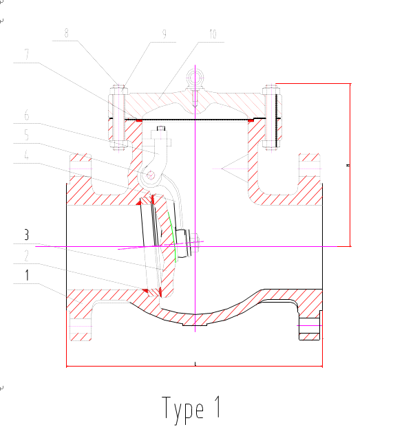
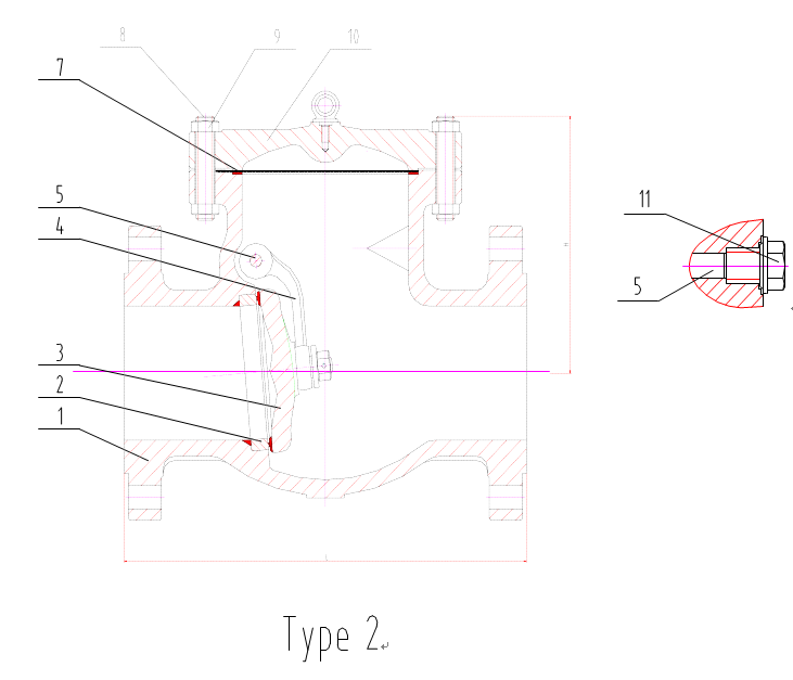
Fig 1 . SWING CHECK VALVE STRUCTURE
-Check valve dimensions and weight refer to YFL Flow Control Co., Ltd.
The user or the pipeline system designer must select valve body material and the class according to the working temperature, working pressure, the type of fluid and standard temperature-pressure rating as specified in ASME B16.34. The manufacturer takes only the responsibilities for use the order material and the valve class, no responsibility for incoherence of user selected material and valve class with the working condition.
Table 1 Valve main parts and materials
ITEM
PART NAME
CARBON STEEL
ALLOY STEEL
STAINLESS STEEL
1
Body
A216 WCB
A352 LCB
A352 LCC
A217 WC6
A217 C5
A351 CF8
A351 CF8M
A351 CF3
A351 CF3M
A351 CF8C
2
Seat Ring
A105
A350 LF2
A350 LF2
A182 F11
A182 F5
A182 F304
A182 F316
A182 F304L
A182 F316L
A182 F321
3
Disc
A216 WCB
A352 LCB
A352 LCC
A217 WC6
A217 C5
A351 CF8
A351 CF8M
A351 CF3
A351 CF3M
A351 CF8C
4
Hinge
A216 WCB
A352 LCB
A352 LCC
A217 WC6
A217 C5
A351 CF8
A351 CF8M
A351 CF3
A351 CF3M
A351 CF8C
5
Hinge Pin
A182 F6
A182 F304
A182 F304
A182 F6
A182 F6
A182 F304
A182 F316
A182 F304L
A182 F316L
A182 F321
6
Bearing Bracket
A216 WCB
A352 LCB
A352 LCC
A217 WC6
A217 C5
A351 CF8
A351 CF8M
A351 CF3
A351 CF3M
A351 CF8C
7
Gasket
Soft Iron+Graphite
304+Graphite
304+Graphite
304+Graphite
316+Graphite
8
Cover Bolt
A193 B7
A320 L7
A320 L7
A193 B16
A193 B16
A193 B8
9
Cover Bolt Nut
A194 2H
A194 4
A194 4
A194 4
A194 4
A194 8
10
Cover
A216 WCB
A352 LCB
A352 LCC
A217WC6
A217 C5
A351CF8
A351 CF8M
A351 CF3
A351 CF3M
A351 CF8C
11
Plug
Carbon Steel
Carbon Steel
Carbon Steel
Carbon Steel
Carbon Steel
Stainless Steel
Table 2 Common used trim material
API 600
Trim No.
Seat ring
Disc sealing
Hinge Pin
1
ER410
ER410
ASTM A182 F6a
2
304
304
ASTMA182F304
5
STL
STL
ASTM A182 F6a
8
STL
ER410
ASTM A182 F6a
9
Monel
Monel
Monel
10
316
316
ASTM A182 F316
12
STL
316
ASTM A182 F316
Table 3 body material suitable for fluid and temperature range
ASTM A216- WCB
ASTM A352- LCB
ASTM A352- LCC
ASTM A217- WC6
ASTM A217- WC9
ASTM A351- CF8
ASTM A351- CF8M
ASTM A351- CF3
ASTM A351 - CF3M
RECOMMEND TEMPERATURE LIMITS
(℃)
-29~427
-46~343
-29~593
-29~537
-29~ 427
-29~ 454
APPLICATION
STEAM, WATER,OI L VAPOUR,
GAS and GENERAL SERVICE
LOW TEMPERATURE SERVICE STEAM,WATER, OIL VAPOUR,GAS
HIGH TEMPERATURE SERVICE STEAM,WATER, OILVAPOUR,GAS
HIGH and LOW TEMPERATURE SERVICE
CORROSION RESISTANCE
Note: where the process fluid is flammable/explosive, it must limit the working temperature of the pipeline system.
6. Working Principle and Structure Description
6.1 Working principle
This serial is sole direction check valve, when fluid flows at normal direction, the disc opens to fluid pressure; when fluid flows converse, the disc closes to the gravity and converse fluid pressure and cut off the bore.
6.2 Structure description
6.2.1 Flange end or but welding end may be selected as to purchaser optimum.
6.2.2 Valves use a reinforced flexible graphite gasket or spiral wound gasket. ..
6.2.3 The 50 bevel seal is used for the valve and the seal material is applied to API 600 or to the customer requirements.
7. Valve Transportation
7.1 Valves are heavy and metal products, care shall be taken to avoid physical injury during transportation. Before transportation, cord and lift device and transportation tool shall be ready, valve package inspected and broken package repaired. Packaging shall conform to specification requirements.
Valve shall be handled with care, no damage the flange end or butt welding end.
7.2 The paint, nameplate and flange sealing surface shall be protected during transportation, no drag valve on the ground especially with the end sealing surface contacted the ground.
7.3 Don't unpack when the valve is not ready for installation at the construction field. The valve shall be placed at a safety location against whether.
8. Valve Storage
8.1 Valve shall be stored in air and dry room with bore blanked and flange sealing surface protected.
8.2 Long-time-stored valve shall be re-inspected prior to use. Close attention shall be paid against sealing damage when removal of dirties for the cleanness of sealing surface. Of necessary, valve shall be pressure tested once more.
9. Valve Installation
9.1 Carefully check valve identification against valve specifications before installation. The fluid flow direction in pipeline must be consistent with the arrow direction indicated on the body.
9.2 If there is pressure pulse/surge source, the check valve shall be installed far away from the source.
9.3 Check the inside of bore and the sealing surface before installation, any attached dirty shall be removed with clean soft cloth.
9.4 For valve with flange end, user shall select proper bolt, gasket according to the working temperature, working pressure and fluid, equally fasten the bolts and nuts. Bolt shall be with full thread and 8UN serial thread shall be used for bolt over 1 inch in diameter.
9.5 For valve with butt-welding end, user shall perform welding and post welding heat treatment using qualified WPS and welder in accordance with the requirements of ASME B31.3.
10. Valve Operation and Maintenance
10.1 The online valve shall not be knocked, walked on or used as weight support.
10.2 Usually check valves have no heat insulation structure, never touch the surface of valves to prevent burn when the valve has a high/low surface temperature.
10.3 After put into service, valve shall be checked and maintained periodically especially for the condition of sealing surfaces and worn, and the corrosion of body. In case of such situation, valve shall be repaired or replaced. It is suggested that inspection and maintenance of valve shall be perform every three months provided the fluid is water or oil, every month or to local law provided the fluid is strong corrosive.
10.4 When performing Repair/maintenance operations, user shall use valve gasket, bolt and nut of the same size and material as the original one. Valve gasket may be ordered as spare parts for maintenance and replacement. It is forbidden to open the bonnet or replace the bolt or nut when the valve contains pressure. After replacement of gasket, bolt and nut, valve shall be pressure tested prior to reuse.
10.5 User may repair the valve-sealing surface providing a successful closure test is performed and the sealing is ok.
10.6 Generally valve trim prefers replacement to reparation. It is better to use provided part as replacement. If part produced by valve manufacturer is not available due to emergency, user shall produce the part to YFL's technical documentation . YFL takes no responsibility for loss caused out of part produced from outsourcing.
10.7 It is not recommended for reparation of valve pressure-containing part by user. If the pressure-containing part is used for a long time and consequently defection occurs and affect safety use, user shall replace the valve with a new one.
10.8 Welding repair on valve online is forbidden.
11. Potential Failure and Troubleshooting
|
Failure |
Cause |
Troubleshooting |
|
Leakage between sealing surfaces |
1. Dirties between sealing surfaces 2. Sealing surfaces damaged |
1. Clean sealing surface 2. Repair the sealing surfaces |
|
Operation failure |
1. Arm device in a wrong position. 2. The wear of arm, disc and pin connection. |
Cut off the fluid and dismount the valve, repair the valve or replace part |
|
|
3. Arm deformation or rupture |
|
|
Leakage between bonnet flanges |
1. Bonnet bolts loose 2. Bonnet gasket failure |
1. Proper tighten bonnet nuts 2. Replace bonnet gasket |
|
Body and bonnet broken and leaked |
1. Water hammer 2. Fatigue 3. Freezing broken |
1. Replace valve that exceeds guarantee period or is found with early fatigue defection 2. Drain away water in winter when valve is not used |
12. Quality Warrant
12.1 YFL warrants its valves to the original purchaser for a period of 18 months from and after the date of delivery to the original customer, against defects in material and workmanship under proper and normal use and service and not caused of resulting from improper application or usage, improper installations, improper maintenance and repairs, modifications or alterations.
12.2 Purchaser shall give notice to YFL upon finding of any defect or assuming defect, YFL has privilege to check the facts of the defect.
12.3 YFL sole obligation under this warranty shall be limited to the follows:
—repair of the material or,
—replacement of the parts and materials or,
—refund the purchase price or collect the defected products from the original purchaser.
12.4 YFL is not responsible to claims caused from unexpected natural disaster such as earthquake, typhoon of any kind arising out of the defect.
12.5 The scope and limitation of warranty can be changed through the agreement between YFL and purchaser.
13. Servicing
13.1 Where contractually specified, YFL Flow Control Co., Ltd. may provide field installation and adjustment.
13.2 YFL will trace the quality of sold valve and provide service to customer requirements..
categories
recent posts
tags
Contact
Scan to wechat:

scan to wechat:


