
YFL Gate Valves Operation and Maintenance Manual
CONTENTS
1.General
2.Essential health & safety requirements of PED/Atex and solution
3.Application and Technical Parameters
4.Valve Structure
5.Main Parts and Material
6.Working Principle and Structure Description
7.Valve Transportation
8.Valve Storage
9.Valve Installation
10.Valve Application and Maintenance
11.Potential Failure and Troubleshooting
12.Quality Warrant
13. Servicing
1. General
1.1 Thanks for your selection of YFL gate valve. As a type of pressure equipment, valve has potential of pressure hazards. It is our obligations that provide you with this instruction for your safety selection, storage, installation,application and maintenance of valve.
1.2 YFL gate valve is regarded as standard product designed to API600 and ASME B16.34, adequate strength is designed according to the class and definite safety allowance is provided. The design, production and inspection of valveisensured by a strict quality assurance system approved by Notified Body.
1.3 The gate valve design of YFL takes no consideration of each specific working condition since it is too wide. The user or the designer of the pipeline system must select correct class and material in accordance with the specialworking condition, or contact with YFL for special design of valve. As common designed valve, consideration shall be paid by the user for the following on selection of valve:
——Whether the pressure-temperature rating is beyond as specified in ASME B16.34.
——The design takes no consideration of traffic, wind and earthquake loading
——The valve design takes consideration of corrosion for normal fluid, with a thickness allowance about 6mm plus the wall thickness as specified in ASME B16.34, no consideration is taken for corrosive fluid.
——The valve design takes consideration of disc sealing wear in accordance with API600 requirements, other wear is not considerate.
——The design takes no consideration of specific fatigue
——The design takes no consideration of reaction forces and moments which result from the supports, attachments, piping, etc.
——The design takes no consideration of pressure raising or suddenly cooling due to decomposition of unstable fluids.
1.4 Upon CE marking requirements and pass the final assessment procedures, valves shall be marked with CE marking, CE marking is eternally fixed on top flange of the body.
2. Essential health & safety requirements of PED/Atex and solution
2.1 What’s YFL design idea
-GATE valve is designed as standard product, no consideration of each specific service condition since its too wide.
-GATE valve is designed to API600, valve has adequate strength according to ASME B16.34 pressure-temperature rating. The GATE valve was EC-type approved by European Notified Body.
-Valve has different sealing materials in accordance with API600, which are corrosion/wear resistance to certain type of fluid.
-Valve contains no light metal (such as Mg) and all parts are electricity conductive and connected together to prevent ignite resource.
-Valve is designed with hand wheel, or gear operator or electric actuator according to its size and torque, and operation requirements.
2.2 What action user shall taken
2.2.1 General
2.2.1.1 In any occurrence, first ensure personnel safety.
2.2.1.2 Use the valves in accordance with ASME B16.34 pressure-temperature rating.
2.2.1.3 Make sure that the selected valve materials are corrosion/wear resistance to the service fluid.
2.2.1.4 Where the service fluid is flammable/explosive, to limit the working temperature.
2.2.1.5 When performing Repair/maintenance operations, make sure that the valves are always depressurized, vented and drained.
2.2.1.6 For actuator operated valves, make sure all supply lines (Electrical, hydraulic, Air) are disconnected before starting any operation.
2.2.1.7 When performing Repair/maintenance operations, always use appropriate protection e.g. protective clothing, (oxygen) masks, gloves, etc.
2.2.1.8 When performing Repair/maintenance operations, do not smoke, do not use any portable no-Ex-proof electrical device in the area and do not use open fire without a valid work permit.
2.2.1.9 Valve must periodically checked on:
-Tightness of bolted connection (body/bonnet, gland, flange connection).
-Corrosion/wear damages (crack, pitting, thickness of the valve).
-Make sure the valves are in fully open/fully closed position.
2.2.2 Specifics
|
Risk |
Preventive Action |
|
Accidental contact with dangerous service fluid* Due to: Gasket or Packing Blow out |
1. See 2.2.1 General |
|
2. Immediately replace Gasket and packing after a Blow-out (use approved/suitable materials only |
|
|
Accidental contact with dangerous service fluid* during disassembly or maintenance operations |
1. See 2.2.1 General |
|
2. After removal from the production line, open and close valve to guarantee depressurized cavity. |
|
|
3. Drain any remainder fluid or substances with suitable devices before disassembly. |
|
|
Structural yielding of valves body with consequent risk of contact with dangerous service medium*, explosion or fire |
1. See 2.2.1 General |
|
2. Create precautions to avoid additional forces on the valves |
|
|
3. Avoid absolutely water hammer: install precaution devices if necessary (e.g. brakes, anti shock devices, etc.) |
|
|
4. Avoid submitting excessive vibrations to the valves. |
|
|
5. Avoid quick Pressure and/or Temperature deviations. |
|
|
Accidental contact with High or Low temperature parts |
1. See 2.2.1 General |
|
2. Predispose apposite insulation on the valve. |
|
|
3. Alert by means of warning signs about risk of burns. |
|
|
4. For Cryogenic-/High Temperature service use only valves equipped with Cryogenic-/High Temp. Extension. |
|
|
Fire or explosion in case of service with flammable fluids |
1. See 2.2.1 General |
|
2. Install only Ex-proof electrical devices in the area |
|
|
3. While performing maintenance in the area, shut down all electrical devices. |
|
|
Explosion in case of oxygen service |
1. See 2.2.1 General |
|
2. Install only Ex-proof electrical devices in the area |
|
|
3. Install and use only valves completely degreased. |
|
|
4. Use valves only made with materials suitable for oxygen service (see EN 1797-1) |
Dangerous service fluid as there are: Toxic-, Corrosive-, Flammable-, High- or Low temperature etc. fluid.
3. Application Scope and Technical Parameters
3.1 Application Scope
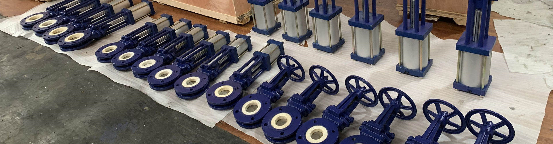
The series valves are widely used in petroleum, chemical, power plant and allied industries for shut off or connection of pipeline.
3.2 Technical Parameters:
Design standard:API600,ASME B16.34
Flange dimension: ASME B16.5
Structure length:ASME B16.10
Nominal pipeline size:50~1200 mm (2~48")
Nominal pressure:20~420 bars (150~2500LB)
Temperature range:see Table 3
Medium:see Table 3
Body material:ASTM material, see Table 1
Trim material: API 600 trim material, see Table 2
Valve testing: API598
4.Valve Structure
Please refer to Figure 1 to 3 for valve structure. Gate valve dimensions and weight refer to YFL.
|
|
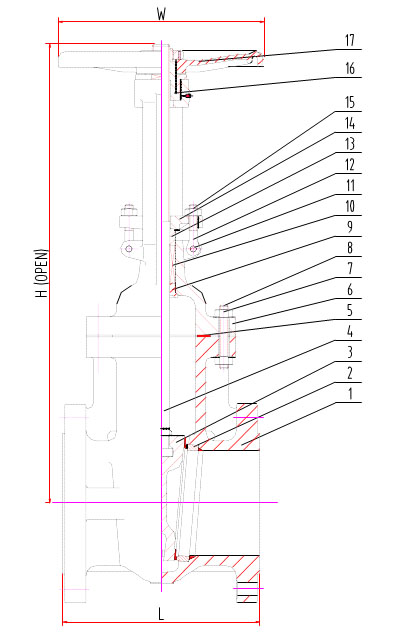
Fig.1150LBGATE VALVE STRUTURE
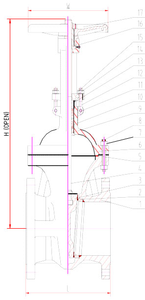
Fig.2 300LB GATE VALVE STRUTURE
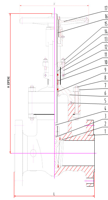
Fig.3 600 LB,900 LB, 1500LB, 2500LB GATE VALVE STRUTURE
5. Main Parts and Material
The user or the pipeline system designer must select valve body material and the class according to the working temperature, working pressure, the fluid and standard temperature-pressure rating as specified in ASME B16.34. The manufacturer takes only the responsibilities for use the order material and the valve class, no responsibility for incoherence of user selected material and valve class with the working condition.
Table 1 Valve main parts and material
|
ITEM |
PART NAME |
CARBON STEEL |
ALLOY STEEL |
STAINLESS STEEL |
||||||||
|
1 |
Body |
A216 WCB |
A352 LCB |
A352 LCC |
A217 WC6 |
A217 C5 |
A351 CF8 |
A351 CF8M |
A351 CF3 |
A351 CF3M |
A351 CF8C |
|
|
2 |
Seat Ring |
A105 |
A350 LF2 |
A350 LF2 |
A182 F11 |
A182 F5 |
A182 F304 |
A182 F316 |
A182 F304L |
A182 F316L |
A182 F321 |
|
|
3 |
Disc |
A216WCB |
A352 LCB |
A352 LCC |
A217 WC6 |
A217 C5 |
A351 CF8 |
A351 CF8M |
A351 CF3 |
A351 CF3M |
A351 CF8C |
|
|
4 |
Stem |
A182 F6 |
A182 F304 |
A182 F304 |
A182 F6 |
A182 F5 |
A182 F304 |
A182 F316 |
A182 F304L |
A182 F316L |
A182 F321 |
|
|
5 |
Gasket |
CL150- 300 |
Soft Iron+Graphite |
304+Graphite |
304+Graphite |
304+Graphite |
316+Graphite |
|||||
|
CL600- 2500 Ring Joint |
Soft Iron |
304 |
304 |
304 |
316 |
|||||||
|
6 |
Bonnet |
A216 WCB |
A352 LCB |
A352 LCC |
A217WC6 |
A217 C5 |
A351CF8 |
A351 CF8M |
A351 CF3 |
A351 CF3M |
A351 CF8C |
|
|
7 |
Bonnet Bolt Nuts |
A194 2H |
A194 4 |
A194 4 |
A194 4 |
A194 4 |
A194 8 |
|||||
|
8 |
Bonnet Bolts |
A193 B7 |
A320 L7 |
A320 L7 |
A193 B16 |
A193 B16 |
A193 B8 |
|||||
|
9 |
Backseat Bushing |
A276 410 |
A276 304 |
A276 304 |
A276 410 |
A276 304 |
A276 316 |
A276 304L |
A276 316L |
A276 321 |
||
|
10 |
Stem Packing |
Braided Graphite & Die formed Graphite Ring |
Braided Graphite & Die formed Graphite Ring |
Braided Graphite & Die formed Graphite Ring |
||||||||
|
11 |
Eye Bolt Pins |
Carbon Steel |
A276 410 |
Stainless Steel |
||||||||
|
12 |
Gland Eye Bolts |
A307 B |
A320 L7 |
A320 L7 |
A193 B16 |
A193 B16 |
A193 B8 |
|||||
|
13 |
Gland |
A276 410 |
A276 304 |
A276 304 |
A276 410 |
A276 304 |
A276 316 |
A276 304L |
A276 316L |
A276 321 |
||
|
14 |
Gland Flange |
A216 WCB |
A352 LCB |
A352 LCC |
A217 WC6 |
A217 C5 |
A351CF8 |
A351 CF8M |
A351 CF3 |
A351 CF3M |
A351 CF8C |
|
|
15 |
Eye Bolt Nuts |
A194 2H |
A194 4 |
A194 4 |
A194 4 |
A194 4 |
A194 8 |
A194 8 |
A194 8 |
A194 8 |
A194 8 |
|
|
16 |
Stem Nut |
A439 D-2 |
A439 D-2 |
A439 D-2 |
||||||||
|
17 |
Handwheel |
Ductile Iron |
Ductile Iron |
Ductile Iron |
||||||||
Table 2 Common used trim material
|
API 600 Trim No. |
Seat ring |
Disc sealing |
Stem |
Back seat |
|
1 |
ER410 |
ER410 |
ASTM A182 F6a |
ASTM A182 F6a |
|
2 |
304 |
304 |
ASTM A182 F304 |
ASTM A182 F304 |
|
5 |
STL |
STL |
ASTM A182 F6a |
ASTM A182 F6a |
|
8 |
STL |
ER410 |
ASTM A182 F6a |
ASTM A182 F6a |
|
9 |
Monel |
Monel |
Monel |
Monel |
|
10 |
316 |
316 |
ASTM A182 F316 |
ASTM A182 F316 |
|
12 |
STL |
316 |
ASTM A182 F316 |
ASTM A182 F316 |
Table 3 body material suitable for fluid and temperature range
ASTM A216-WCB
ASTM A352- LCB
ASTM A352- LCC
ASTM A217- WC6
ASTM A217- WC9
ASTM A351- CF8
ASTM A351- CF8M
ASTM A351- CF3
ASTM A351
- CF3M
RECOMM END TEMPER ATURE LIMITS
-29~427
-46~ 343
-46~ 343
-29~ 593
-29~ 593
-29~ 537
-29~ 537
-29~ 427
-29~ 454
APPLICA TION
STEAM,WAT ER,OIL VAPOUR,GAS
and
GENERAL SERVICE
LOW TEMPERATUR E SERVICE
STEAM,WATER
,OIL VAPOUR,GAS
HIGH TEMPERATUR E SERVICE
STEAM,WATE R,OIL VAPOUR,GAS
HIGH and LOW TEMPERATURE SERVICE
CORROSION RESISTANCE
6. Working Principle and Structure Description
6.1 Working principle
The series valve is straight pattern one. When hand-wheel rotate clockwise, the gate descends and the valve shuts off; when rotate counter clockwise, the gate ascends and the valve opens.
6.2 Structure description
6.2.1 Flange end or but welding end may be selected as to purchaser optimum.
6.2.2 Packing seal structure and flexible graphite combination packing is used for the series valve.
6.2.3 Class 150LB/300LB valves use a reinforced flexible graphite gasket and 600 to 2500LB valves use ring joint metal gasket.
6.2.4 The wedge seal is used for the valve and the seal material is applied to API 600 or to the customer requirements.
6.2.5 Hand-wheel or bevel gear is common used as operator. please see YFL’s catalogue.
7. Valve Transportation
Before transportation, cord and lift device and transportation tool shall be ready, valve package inspected and broken package repaired. Packaging shall conform to specification requirements, it is forbidden to rotate the handwheel when valve is packaged. Valve shall be in full-close status. For mis-opened valve, the sealing surface shall be cleaned and valve re-closed and ends of bore blocked. Actuator and valve shall be packaged separately.
During transportation or lifting, cord shall be tied to the yoke, no tied to the hand-wheel or stem. Valve shall be handled with care, no bump to other thing.
The paint, nameplate and flange sealing surface shall be protected during transportation, no drag valve on the ground especially with the end sealing surface contacted the ground.
Don't unpack when the valve is not ready for installation at the construction field. The valve shall be placed at a safety location against rain and dust.
8. Valve Storage
8.1 Valve shall be stored in air and dry room with bore blanked for protection.
8.2 Long-time-stored valve shall be re-inspected prior to use. Close attention shall be paid against sealing damage when removal of dirties for the cleanness of sealingsurface. Of necessary, valve shall be pressure tested once more.
9.Valve Installation
9.1 Carefully check valve identification against operation requirements before installation.
9.2 Check the inside of bore and the sealing surface before installation, any attached dirty shall be removed with clean soft cloth.
9.3 Check the sensibility of actuator to prevent block before installation.
9.4 Valve operation device is recommended to be installed at location 1.2m from the ground for convenient of operation. Where the center of valve and the hand-wheel is over 1.8m from the ground, a platform shall be built for the frequently operated valve. For pipeline with numbers of valves, valves shall be installed on the same platform as likely as possible for convenient of operation.
9.5 For single valve installed at location over 1.8m and less operated, apparatus may be used such as chain-wheel, extension bar, move platform and move ladder etc. Where valve is installed underground, extension bar or ground-well shall be set. For safety reason, the ground-well shall be covered.
9.6 For valve installed on horizontal pipeline, the stem is suitable at uprightness position; or, the downward stem shall be inconvenience for operation and maintenance, as well the valve is liable to corrosion. If the ground valve slant installed, operation and maintenance shall also be inconvenience.
9.7 When valves are installed in pipeline side by side, enough space shall be considerate for operation, maintenance and dismantle. The clearance of hand-wheels shall not less than 100mm; in case of narrow clearance, valves shall be installed interleaving.
9.8 For valve with flange end, user shall select proper bolt, gasket according to the working temperature, working pressure and fluid, equally fasten the bolts and nuts. Bolt shall be with full thread and 8UN serial thread shall be used for bolt over 1 inch in diameter.
9.9 For valve with butt-welding end, user shall perform welding and post welding heat treatment using qualified WPS and welder in accordance with the requirements of ASME B31.3.
10. Valve Application and Maintenance
10.1 After installation and for the pressure test of the pipeline or the system, the disc must be fully opened or fully closed. It is not recommended to partly open the valve for adjustment of flow rate or emergent pressure relief blow-off.
YFL is not responsible for damage, loss or expense arising out of such usage.
10.2 Dust, grease and medium residual trend to accumulate at the surfaces of body, stem, the trapezoid thread of stem nut, the guide of yoke and gears etc, wear and erode the valve, and shall be cleaned frequently.
10.3 After put into service, valve shall be checked and maintained periodically especially for the situation of sealing surfaces and worn, the age of packing and the corrosion of body. In case of such situation, valve shall be repaired or
replaced. It is suggested that inspection and maintenance of valve shall be perform every three months provided the fluid is water or oil, monthly or to local law provided the fluid is strong corrosive.
10.4 Upon reparation, valve shall be re-assembled and adjusted and sealing tested, meanwhile the replaced parts shall be listed for reference.
10.5 User may select valve packing, gasket, bolt and nut of proper size. Valve packing and gasket may be ordered as spare parts for maintenance and replacement. It is forbidden to open the bonnet or replace the bolt, nut or packing
when the valve contains pressure. After replacement of packing, gasket, bolt and nut, valve shall be closure test prior to reuse.
10.6 User may repair the valve-sealing surface providing a successful closure test is performed and the sealing is ok.
10.7 Generally valve trim prefers replacement to reparation. It is better to use provided part as replacement. If part produced by valve manufacturer is not available due to emergency, user shall produce the part to YFL's drawing and
inspect prior to replacement. YFL takes no responsibility for loss caused out of part produced other than YFL.
10.8 It is not recommended for reparation of valve pressure-containing part by user. If the pressure- containing part is used for a long time and consequently defection occurs and affect safety use, user shall replace the valve with a
new one.
10.9 Welding repair on valve online is forbidden.
10.10 The online valve shall not be knocked, walked on or used as weight support.
10.11 A safety label shall be set or the valves shall be isolated from environment when the surface temperature on the valve body is high.
11. Potential Failure and Troubleshooting
|
Failure |
Cause |
Troubleshooting |
|
Leakage of packing |
1. Gland flange nuts loose 2. Rings of packing not enough 3. Packing aged or failure 4. Stem sealing damaged |
1. Equally tighten eyebolt nuts 2. Add packing 3. Replace packing 4. Stem shall be maintained periodically by reparation or replacement conjunction with the maintenance of pipeline facilities |
|
Leakage between sealing surfaces |
1. Dirties between sealing surfaces 2. Sealing surfaces damaged |
1. Clean sealing surface 2. Repair the sealing surfaces |
|
Operation failure |
1. Packing too tight 2. Thread of stem nut over worn 3. Stem bent 4. Foreigner existence between stem and stem nut or gland or gland flange |
1. Proper loose gland flange nuts 2. Replace stem nut 3. Rectify or replace stem 4. Clean foreign matter |
|
Leakage between bonnet flanges |
1. Bonnet bolts loose 2. Bonnet gasket failure |
1. Proper tighten bonnet nuts 2. Replace bonnet gasket |
|
Body and bonnet broken and leaked |
1. Water hammer 2. Fatigue 3. Freezing broken |
1. Carefully operation to prevent suddenly stopping pumping and rapidly shutting. 2. Replace valve that exceeds guarantee period or is found with early fatigue defection 3. Drain away water in winter when valve is not used |
|
Disc failed to open |
1.Disc blocked in the body. 2.Stem is overheated and |
1. Use proper torque 2. When the valve is closed and |
12. Quality Warrant
12.1 YFL warrants its valves to the original purchaser for a period of 18 months from and after the date of delivery to the original customer, against defects in material and workmanship under proper and normal use and service and not caused of resulting from improper application or usage, improper installations, improper maintenance and repairs, modifications or alterations.
12.2 Purchaser shall give notice to YFL upon finding of any defect or assuming defect, YFL has privilege to check the facts of the defect.
12.3 YFL sole obligation under this warranty shall be limited to the follows:
—refund the purchase price or collect the defected products from the original purchaser.
12.4 YFL is not responsible to claims caused from unexpected natural disaster such as earthquake, typhoon of any kind arising out of the defect.
13.Servicing
13.1 Where contractually specified, YFL may provide field installation and adjustment.
13.2 YFL will trace the quality of sold valve and provide service to customer requirements.
categories
recent posts
tags
Contact
Scan to wechat:

scan to wechat:


